
The Turing Bombe
Frank Carter
Introduction
The successes in breaking Enigma ciphers at Bletchley Park contributed greatly to the defeat of the Axis powers and significantly shortened the duration of the war.
In breaking these ciphers the Bombes had a hugely important role by transforming the process of breaking the German cipher messages from slow hand based procedures to one that resembled the operation of an industrial production line.
Frank Carter
At its peak this operation enabled some 4000 messages to be broken every day and provided the Allies with unprecedented levels of intelligence about the intentions of the enemy.
During the course of the war over 200 bombes were constructed and used operationally to break the cipher messages transmitted by all three branches of the German Armed Forces. Some of the messages transmitted by the German Abwehr (Secret Service) were also broken by means of the Bombes.
At the end of the war most of the machines were destroyed although a small number were retained for a few years before they too were scrapped, so that finally none survived. The extreme levels of secrecy surrounding the wartime activities at Bletchley resulted in the public being totally unaware of what had transpired there and of the remarkable technical innovations that had taken place.
It was only after the security embargo was lifted in 1974 that it became evident that machines had played an important role in the ‘code-breaking’ work that had provided the wartime ‘Ultra’ intelligence, but no details were revealed about them or the tasks which they carried out.
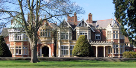
The Mansion in Bletchley Park
Some years later in 1992 the Bletchley Park Trust was set up to establish a permanent Museum as a tribute to the remarkable people who worked at BP and to commemorate their achievements and successes.
Since none of the original Bombes had survived it was decided to set up a project that it was hoped would ultimately lead to the construction of a working machine. This hugely ambitious task started in 1995 when GCHQ released the engineering drawings of the Bombe to the Trust. In July 2007 the newly completed machine, appropriately named ‘Phoenix’, was officially commissioned by H.R.H the Duke of Kent.
This article does not attempt to describe the building of this machine; the task has taken some twelve years to complete and was carried out by a group of dedicated engineers under the leadership of John Harper. For detailed information about this please refer to the following website: www.jharper.demon.co.uk/bombe1.htm
The Bombe was an essential tool in the process of breaking Enigma signals; it is not a computer, and it does not perform numerical calculations. Its wartime function was to carry out a systematic search based upon certain logical considerations, to find parts of the Enigma keys that had been used to encipher the intercepted messages. These keys were changed regularly at least once every day.
A brief description of the Enigma machine
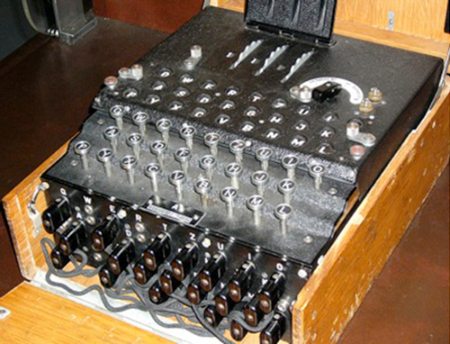
A 3-rotor Enigma machine
The Enigma machine generates cipher-text from the corresponding sequence of plain-text typed on its keyboard. When a letter key is depressed the movement first causes one or more of the rotors in the machine to move and then closes a switch under the key to complete an electrical circuit that lights a lamp (one from a panel of 26 lamps) to indicate the corresponding cipher-text letter. The convoluted wiring of the circuit passes through the interior of the rotors, and also through a device known as the plug-board. As a consequence of the movement of the rotors, the internal circuits connecting the keys to the lamps change at every keystroke.
Details about the rotors
Each rotor has a set of 26 electrical contacts on its two opposite sides, with a different arrangement of 26 internal wires connecting the contacts on one side to those on the other. When they are located in the machine each combination of the rotational positions of the three rotors will create a different electrical circuit between the keys and the indicating lamps. The three rotors turn in a way that resembles the motion of the wheels in an odometer fitted in a car, the right-hand rotor turning on by one position for each letter key pressed, and at a particular position, this turning motion causes the middle rotor to turn on by one place. In the same way at a certain position the movement of the middle rotor causes the left-hand rotor to turn on by one place.
The rotor orientations where the ‘turn-overs’ take place are determined by the positions of a notch cut into the side of the ring that is fitted round the rim of each rotor, rather like a tyre on a wheel. These rings either have the 26 letters (A–Z) or alternatively the 26 numbers (01–26) inscribed on them (the following exposition will assume them to be letters).
The ring-settings
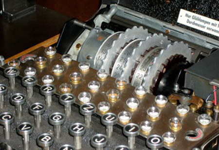
Interior showing the lamps, rotors and reflector
During the initial setting up of the machine each ring is rotated around the inner core of its rotor to a position where a chosen letter on the ring is aligned with a fixed index mark embossed on the rotor, and it is then locked at this position by a spring clip. These chosen positions are referred to collectively as the ‘ring-settings’ of the rotors and as the plain-text is ‘typed’ on the keyboard of the machine the ‘turn-over’ positions of the middle and left-hand rotors are determined by these settings.
The rotor core starting positions
The three rotors (taken from the five available) are placed side by side in one of the six possible arrangements. When in position, three small viewing windows allow one letter on each of the rotor rings to be visible to the operator. The rotors are then turned by hand until the three letters chosen for the initial rotor starting positions appear in the three windows. The initial rotor starting positions together with the ring-settings define the initial orientations of the wiring cores in the three rotors known as the ‘rotor core starting positions’.
An important point in understanding the operation of the Bombe is that the ‘rotor core starting positions’ can be defined by many different combinations of ring-settings and initial starting rotor positions. For example the ring settings ‘ABC’ and initial rotor starting positions ‘HNT’ define the same set of ‘rotor starting core positions’ as the ring settings ‘ZZZ’ and initial rotor starting positions ‘GLQ’.
After passing through the three rotors the electric circuits are connected to another device known as the ‘reflector’; the internal wiring in this has the effect of returning the circuit back through the rotors for a second time but in the reverse direction and following a different path. The following diagram gives the basic structure of the complete machine. (The rotors and the reflector are sometimes referred to as the ‘scramblers’.)
The function of the plug-board
The plug-board consists of a panel of twenty-six double sockets (A–Z), mounted on the front of the machine. The pairs of sockets for chosen pairs of letters are electrically connected together by means of external cables fitted with the appropriate plugs at each end.
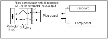
The basic structure of an Enigma machine
For the pairs of letters that are connected together in this way, the plug-board has the effect of cross-connecting the wiring for the letters in each pair in the circuit between the keyboard and the rotors and also between the rotors and the indicating lamps.
For example suppose that the sockets for the letters D and G are so connected, then by means of the plugboard, key ‘D’ on the keyboard will be electrically connected to terminal G on the commutator, and likewise key ‘G’ on the keyboard will be connected to terminal D. In the same way if the scrambler output arrives at terminal D on the commutator then it will be subsequently connected to lamp G, and likewise a scrambler output to terminal G on the commutator will be connected to lamp D.
The ‘steckers’
The pairs of pre-selected letters subjected to these exchanges were known at BP as the ‘stecker pairs’ (‘stecker’ is the German word for ‘plug’). The remaining letters not paired for this purpose were said to be ‘self-steckered’ or ‘unsteckered’. Thus in the above example the letters D and G are a stecker pair represented as D/G.
During the war the standard German practice was to select 10 pairs of letters each day, and one of the tasks at BP was to identify these 10 ‘stecker pairs’ (by default the remaining six letters would be ‘self-steckered’).
The reciprocal nature of the Enigma machine
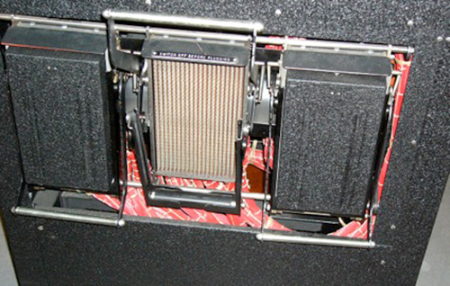
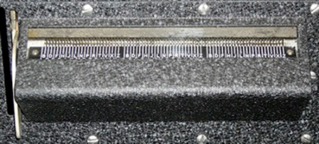
The detachable reflector boards in the Bombe, with the middle board removed. These mimic the Enigma reflector.
The Enigma machine was designed to have reciprocal characteristics so that the two processes of enciphering and deciphering a message are essentially the same.
This was achieved by the reversible nature of the electrical circuit brought about by means of the reflector. The reciprocal characteristic of the machine implies that a cipher message made on one machine can be restored back to plain-text by typing the cipher text on a second machine provided that this has initially been set up in the identical way to the first one using the same key.
The Enigma keys
The keys used by German Army and Air Force consisted of the following four parts:
(i) The rotor order: i.e. the identity of the three Enigma rotors that had been used and their locations (left, middle, right) in the machine. (There were five different rotors available for use, giving 60 possible rotor orders.)
(ii) The rotor ring-settings: These determined the ‘turn-over’ positions of the selected rotors. (There are 26x26x26 = 17,576 possible ring-settings.)
(iii) The ‘steckers’: i.e. the identity of the set of ten pairs of letters that had been selected for the plug-board connections on the Enigma machine. (There are approximately 150, 000,000,000,000 possible sets.)
(iv) The ‘message-settings’: i.e. the starting positions of the three rotors (as shown on the rotor rings) that had been used when the message was originally enciphered. (There are 26 x 26 x 26 = 17,576 possible ‘message-settings’.)
Although the ring-settings are part of the key they do not contribute to the number of possible electrical configurations of the Enigma machine. Even so the number of configurations is extremely large and is equal to the product:
60 x 150,000,000,000,000 x 17,576
(approximately 1.58 x 10²⁰).
The function of the Bombe
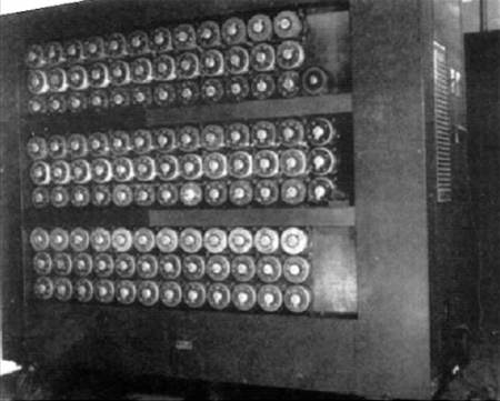
A wartime photograph of a 3-rotor Bombe. This is one of the few pictures available, and shows a special version of the Bombe fitted with an extra indicator drum. This machine helped to break the ‘Abwehr’ Enigma cipher messages transmitted by the German Secret Service.
The Bombe was designed to carry out a systematic search to determine the following components of an Enigma key: the rotor order, the ‘rotor core starting positions’, and some of the ‘steckers’.
At BP the unknown ring-settings were initially assumed to be ‘ZZZ’ and only at the last stage of the work after the true ring-settings had been determined was it then possible to deduce the original ‘message settings’ from the ‘rotor core starting positions’.
Searching for the keys
Bearing in mind the huge number of possible keys, if a search was to be carried out then it was essential that a procedure be found that would greatly reduce the size of the ‘key space’ that was involved. Alan Turing devised such a procedure that depended on a ‘crib’ of the part of the plain-text of the enciphered message. This reduced the size of the ‘key space’ to a little over one million, and remarkably did not require any prior knowledge of the ‘steckers’.
Cribs and menus
A crib is a sequence of letters from the plain-text of a message that can be matched one to one with some of the letters from the cipher-text. It was possible to find cribs for certain routine messages because they frequently contained stereotyped text.
For example the routine W/T test tuning messages that were transmitted often began with the plain-text ‘DASXISTXEINXABSTIMMSPRUQ’, and provided the basis for valuable cribs. (The Enigma operators frequently used an ‘X’ to represent a ‘space’.)
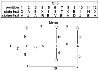
A crib and menu
After the set of letters in the crib had been correctly aligned with the corresponding set of letters from the cipher text, a diagram known as a ‘menu’ could be constructed showing the relationships between the two sets of letters. A simple example of a menu is shown to the right.
The menu, in the form of an electric circuit, was ‘plugged up’ on the panel of sockets located on the back of the Bombe by means of 26-way cables.
Early on in the War, when the searching procedure was carried out using the first prototype Bombe, it was essential that the structure of the menu included multiple ‘closures’ or loops. The crucial function of a menu loop in the searching procedure is best explained by means of an illustrative example.
In the given menu the sequence of letters: S → A → X → V form one such loop, and the diagram below gives the details of the Enigma enciphering processes that correspond to the four links in this loop. In this diagram the four unknown stecker partners of the letters S, A, X and V are respectively represented by the Greek letters: α, β, γ and δ. (The Enigma rotor systems and their equivalents on the Bombe will subsequently be referred to as the ‘scramblers’. The scrambler connections were made with 26-way cables.)
The logic used in a search
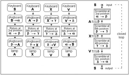
Details of the four successive Enigma encipherments for the menu loop S → A → X → V
Turing’s searching procedure exploited the symmetrical relationship that exists between the stecker pairs of letters appearing in the loop; for example S steckered with α implies α steckered with S. This relationship enables the stages of the enciphering process in the four links of the loop to be combined into the much simpler sequence of Enigma rotor systems also shown in the diagram.
The sequence of scramblers illustrates two important facts:
(i) Only the stecker partners of the letters from the menu are enciphered by the scramblers; the letters on the menu are not involved in the process.
(ii) Since the scrambler sequence forms a closed loop the input and output letters must be the same (≡ α) and the identity of the unknown stecker letters (β, γ, δ) are determined solely by the identity of letter α and not on the letters A, X and V from the menu.
It follows that if α, the unknown stecker partner of letter S, can be identified, then the stecker partners of the other letters A, X and V can be easily found from the sequence of scramblers.
Testing hypotheses in order to identify the unknown stecker letter α:
If it is assumed that the rotor order and settings are both correct, then the validity of a hypothesis about the identity of α, can be tested electrically by means of the sequence of scramblers shown in the diagram.
Suppose that the hypothesis is: α ≡ K. This can be tested by connecting a source of electrical voltage to wire K at the input so that the voltage is carried through the wiring in the sequence of scramblers to appear on a single wire at the output. If this also happens to be wire K then the conclusion reached will be that: α ≡ K.
The fact that the conclusion is in agreement with the initial hypothesis is a clear indication that the hypothesis is true.
Suppose another hypothesis α ≡ R is tested so that the voltage source is connected to wire R at the input and after passing through the scramblers, appears on wire F at the output. In this case the hypothesis α ≡ R has resulted in the logically inconsistent conclusion α ≡ F, indicating that this hypothesis is false.
From this example it should be evident that by testing a sequence of up to twenty-six alternative hypotheses: (α ≡ A), (α ≡ B), (α ≡ C)..... (α ≡ Z), it will be possible to determine the correct stecker partner of letter S by finding the only hypothesis that leads to a logically consistent conclusion.
However this procedure (referred to by Turing as ‘single line scanning’) would take too long to carry out to be of great practical value. What was urgently needed was a technique that would provide ‘simultaneous scanning’, so that all twenty-six of the possible alternative hypotheses could be tested at the same time, thus enabling the true one to be identified almost instantaneously.
In his wartime ‘Treatise on Enigma’ Turing included the following statement. (In the example S is what Turing called the ‘central letter’.)
There is however no reason why, when from one hypothesis about the stecker partner of the central letter we have deduced that the central letter must have another stecker value, we should not go on and draw further conclusions from this second stecker value. At first sight this seems quite useless, but, as all the deductions are reversible (i.e. can be used as new hypotheses) it is actually very useful, for all the conclusions that can be drawn will then be false, and those that remain will stand out clearly as possible correct hypotheses.
Voltage feedback
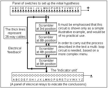
The feedback process
The diagram shows how this ingenious idea was implemented in a relatively simple way by means of some additional electrical connections (i.e. ‘voltage feedback’).
The ‘feedback’ connections enabled the conclusion obtained from the initial hypothesis to be used as a new hypothesis and in turn for its conclusion to be used for another new hypothesis, and so on until the process had been exhausted. The circuit shown is based upon the single loop from the menu previously used. The initial hypothesis is chosen by setting the corresponding switch on the panel, and the relays in the indicator unit that then become energised to indicate all the consequent logical conclusions.
Finding the correct hypothesis
In practice if this technique is applied to a simple menu consisting of a single loop as shown, only a proportion of the twenty-five possible false conclusions will be obtained and it order to be sure of generating all of them it is necessary to use a more complex menu that has at least three loops in its structure.
If by chance the initial hypothesis happens to be true then the only outcome will be one conclusion confirming the truth of the hypothesis (i.e. α ≡ K ⇒ α ≡ K).
So far it has been assumed that the rotor order and settings used are both correct. However when the Bombe carried out a systematic search for part of an Enigma key, these assumptions would, with the exception of the one special case just considered, always be wrong! If the rotor order or the message settings are wrong then at any stage of the process the output letter derived from any input letter can be considered to be random, and consequently all the relays in the indicator unit have approximately equal chances of being activated. This means that by means of the feedback process described earlier, it is highly likely that ultimately all the relays will be activated, although there will be a few occasions when by chance not all of them will be activated.
Summary
If the rotor order and settings are both correct then there are two possible outcomes:
(i) Initial hypothesis false: all but one of the twenty-six relays will be energised.
(ii) Initial hypothesis true: only one relay is energised.
If the rotor order or settings are wrong (i.e. in all cases except one!) then there are two possible outcomes for any initial hypothesis (true or false):
(i) All of the relays in the indicator unit will be energised.
(ii) On a few occasions not all of the relays will be energised.
Bombe ‘stops’
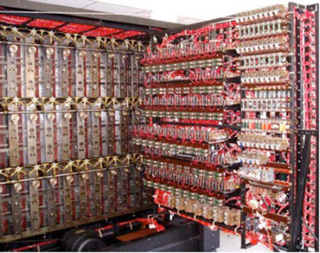
Interior view of Bombe with the hinged back panel open
For each rotor order tested, the Bombe is designed to systematically run through all of the 17,576 positions of the scramblers and to stop whenever less than twenty-six relays are energised (the original Bombe operators referred to this event as a ‘stop’). This implies that a stop would occur when the rotor order and settings were both correct (known as a ‘good’ stop) or by chance on a few other occasions when the rotor order and settings were wrong (these were known as ‘false’ stops).
The number of false stops obtained depends upon the structure of the menu. During the War a typical menu used on the Bombe was expected to produce about four false ‘stops’ for each rotor order that was tested.
Every Bombe ‘stop’ provides the following three parts of a possible Enigma key:
The rotor order, the rotor core starting positions, the stecker partner for one letter on the menu (the stecker letter was found by inspecting the relays in the indicator unit).
If the ‘stop’ is false then so would be the information it provided, but this would not be immediately obvious to the Bombe operators.
Eliminating false ‘stops’
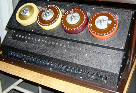
The checking machine. The drum on the left serves as a pre-set reflector, the other three drums with adjustable letter rings emulate the rotors from an Enigma machine.
During the War in order to eliminate the false stops, the validity of all of them had to be checked. This was done by determining the stecker partners of the other letters on the menu that were implied by the information provided by the ‘stop’, the work being carried out with the aid of a device known as a ‘Checking machine’. The steckers pairs found in this way were then examined to see if there were any logical inconsistencies between them, and if any were found then the stop would be rejected as false.
For example suppose the stecker pairs A/G and V/G were found in this way, as these are logically inconsistent with one another they show that the ‘stop’ is false.
Diagonal board
A serious operational difficulty with the prototype bombe was that to enable simultaneous scanning to take place it was essential that the menu used contained at least three loops. This was a very restrictive condition and it was found that only a small proportion of the intercepted messages provided such menus. Consequently the Bombe would only have been of limited use unless a way had been found to significantly improve its performance.
Gordon Welchman, another mathematician from Cambridge, realised that the symmetry property of each pair of stecker letters could provide a new way of deriving conclusions from an initial stecker hypothesis that did not require the presence of loops in the menu. His brilliant idea resulted in some additional circuits known as the ‘diagonal board’ being incorporated in the second version of the Bombe. With this improved machine it was possible to successfully use menus with only a single loop or in special circumstances, with no loops at all.
Bombe drums with their letter rings. Note the anti-clockwise sequence of letters on the fixed reference rings.
According to Joan Murray, a gifted young mathematician who worked on the Bombe, Welchman’s original objective had been to make it easier to use menus with two or more unconnected networks that sometimes occurred. At the time both Welchman and Turing were urgently seeking a general method for achieving ‘simultaneous scanning’ that did not rely upon the presence of multiple loops in the menus, and Turing soon realised that the diagonal board would make this possible.
The diagonal board was an immensely important development. When it was brought into operation in the Mk II version of the Bombe it became possible to use many more of the available menus than would otherwise have been the case; it also had the effect of significantly reducing the numbers of random ‘stops’.
One practical form of the diagonal board consists of a square lattice of 26 x 26 electrical terminals in which the 26 rows are used to represent any of the letters A–Z that may occur on a menu and the 26 columns are used to represent the 26 possible stecker partners of these letters. Pairs of these terminals are permanently connected together to correspond to the symmetrical property of the steckers, so that for example the terminal in row F, column j is connected to the terminal in row J, column f. The name of the diagonal board probably arose from the geometrical pattern formed by the wiring.
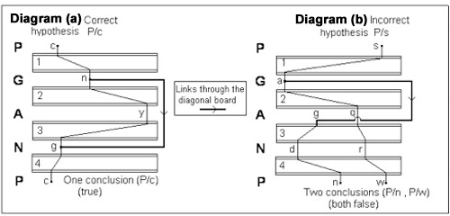
The diagonal board
A simple illustrative example to show the effect of the diagonal board is given in the diagrams on the right of the scrambler system for a single loop P → G → A → N from another menu, these show a few of the individual wires in the 26-way cables connecting the scramblers together. In both diagrams the scramblers are at their correct positions. (In order to minimise the risk of confusion the stecker partners of the letters on the menu are shown in lower case.)
Diagram (a) shows the voltage path when the initial hypothesis is correct (P is steckered to c), and the conclusion obtained confirms this. Note that the additional link through the diagonal board has had no effect on the outcome as it only joins together two points that are already on the same electrical path.
Diagram (b) shows the voltage path when a wrong initial hypothesis is used (P is steckered to s), leading to the false conclusion: P is steckered to w. In this case another link through the diagonal board generates a second false conclusion (P steckered to n). The numerous additional links provided by the diagonal board usually generate large numbers of false conclusions from a false hypothesis, but do not compromise the true one.
In summary, the use of the diagonal board greatly increased the number of false conclusions derived from any false initial hypothesis so that it became possible to achieve simultaneous scanning with much less complex menus. Turing’s original procedure described earlier could achieve this, but only if the menus used had at least three loops in their structure. In practice it was found very difficult to construct menus of this type from the wartime cribs that were available.
The condition required for the diagonal board to achieve the same effect was much less severe and simply consisted of a lower permissible limit for the number of letters on a menu, although the presence of one or more loops was still highly desirable. The other great benefit was a considerable reduction in the number of false ‘stops’ obtained from most menus.
The Bombe: physical details
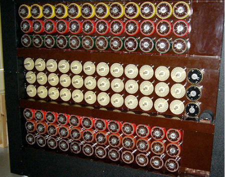
Front face of the Bombe at Bletchley Park with two banks of drums in position. The three indicator drums are located to the right of the empty middle bank.
Essentially the Bombe is an electro-mechanical machine operating under the control of a complex system of electric relays. The wartime machines were manufactured by the British Tabulating Machine Company at Letchworth, under the direction of Harold ‘Doc’ Keen the Chief Engineer, and by the end of the war over two hundred of them were in operation.
On the front of the machine there are 36 sets of three ‘drums’ arranged vertically in three banks of twelve, each set of three drums corresponding to the three rotors in an Enigma machine. The sets of three drums form the ‘scrambler units’ that are incorporated in the complex electrical circuit for the menu that is ‘plugged up’ on the panel of sockets located at the back of the machine.
Inside each drum there are two separate sets of the wiring for the rotor it emulates, and consequently there are 2x2x26 (=104) electrical contacts on the rear face of each drum.
The duplicated wiring is needed in order to make the scramblers in the Bombe electrically symmetrical so that the currents in the individual wires of the menu circuit can pass through the scramblers in either direction. The drums are mechanically connected to common drive shafts through a system of cams and gear wheels, and rotate at three different speeds. The prime mover is a 0.75 H.P DC electric motor.
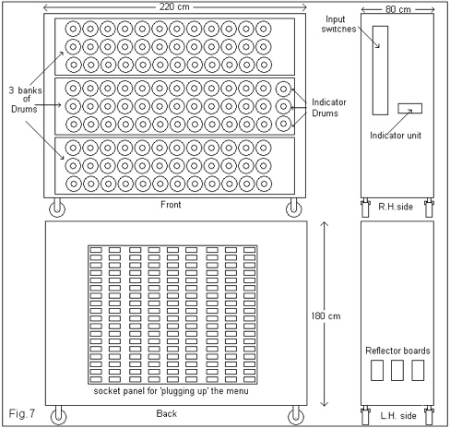
The Bombe
The dimensioned diagram on the right gives some idea of the size of the machine.
Parallel processing
On the Bombe it is possible to set up a particular menu in triplicate with different sets of drums by making use of the three banks of locations available for them on the front of the machine. During the War this was done so that it is possible to test three different possible ‘rotor orders’ at the same time. The three ‘reflector boards’ required for this are mounted on the left hand side of the machine, the wiring on each board being equivalent to that in twelve Enigma reflectors.
When the Bombe is in operation the drums systematically rotate through all of the possible setting positions, and the time taken to complete this procedure (originally known as a ‘run’) is approximately 18 minutes.
The drums are detachable and are colour coded to correspond to the five Enigma rotors they emulate; for example the drums coloured red, maroon and green correspond respectively to the Enigma rotors I, II and III.
Setting up the Bombe
The initial hypothesis is chosen by first selecting a suitable letter from the menu (letter S in the example) and then connecting the bank of twenty-six switches (labelled A to Z) that is mounted on the right-hand side of the machine, to a position on the menu circuit corresponding to this letter. The stecker partner for this letter is selected by setting one of these switches to ‘on’.
As the validity of the initial hypothesis is immaterial, usually switch A is set, so that the ‘test voltage’ is connected to the chosen position on the wiring of the menu circuit. (In the example this would be to wire A on the input to the scrambler at position S on the menu.)
Initially the three drums in each scrambler are turned (by hand) to the designated positions shown on the menu. These are all relative to the positions of the three drums in the scrambler being used for the ‘first position’ on the menu. Since the true settings for the ‘first position’ are unknown they are assumed to be ZZZ, so all of the other scrambler drums are adjusted accordingly to be at the correct relative positions to ZZZ.
When the machine is in operation it will repeatedly carry out Turing’s process, advancing the drums in the scramblers by one place each time. Whenever the machine detects the necessary conditions (i.e. those previously described) it will automatically stop. Usually in the searching process, many different rotor orders have to be tested and the machine will stop a number of times; however only one of these ‘stops’ will provide the correct information for a part of the Enigma key.
The Bombe in action
Positions |
1 |
2 |
3 |
4 |
5 |
6 |
7 |
8 |
9 |
10 |
11 |
12 |
13 |
14 |
15 |
16 |
Cipher |
S |
N |
M |
K |
G |
G |
S |
T |
Z |
Z |
U |
G |
A |
R |
L |
V |
Plain |
W |
E |
T |
T |
E |
R |
V |
O |
R |
H |
E |
R |
S |
A |
G |
E |
At Bletchley Park the first public demonstrations of the re-built bombe were made with a wartime menu derived from a crib for a weather forecast that had originally been used for the training of the WREN operators. This crib contains sixteen letter pairs as shown on the right.
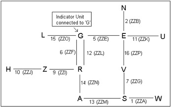
A menu
In order to obtain a menu consisting of a single connected ‘web’, thirteen of these letter pairs were selected resulting in the menu shown in the diagram on the right.
Scrambler settings: positions and offsets
In this menu some of the information relating to the scrambler settings requires further explanation. In the simple menu described previously the relative positions of the scramblers were represented by the corresponding positional numbers of the letter pairs as given in the crib. However in practice the Bombe operators set up these initial positions by means of circular reference scales of letters (A – Z) mounted on the faces of the drums, and the table on the right shows some examples of the way in which this was done.
Positional number |
Drum letter positions |
Positional number |
Drum letter positions |
0 |
ZZZ |
26 |
ZAZ |
1 |
ZZA |
27 |
ZAA |
2 |
ZZB |
28 |
ZAB |
3 |
ZZC |
29 |
ZAC |
… |
… |
… |
… |
25 |
ZZY |
51 |
ZAY |
In the table the positions ZZZ correspond to the original positions of the Enigma rotors before the first letter of the message had been enciphered, so that the drum settings ZZZ correspond to the original Enigma ‘rotor core starting positions’ that had been used. For this reason all of the scrambler positions shown in the menu were known as the ‘offsets’ (i.e. the number of positions in front of the unknown ‘rotor core starting positions’). For example position 2 on the menu would have the offset ZZB.
For the demonstration of the Bombe at BP this menu was ‘plugged up’ on the rear face of the machine, with the indicator unit connected to location G on the menu, and the ‘test voltage’ applied to relay A in the indicator unit, so that the initial hypothesis was ‘G is steckered to A’. The correct rotor order was already known to be:
Upper drum: II (2), Middle drum: V (5), Lower drum: III (3).
(These correspond to the Left-hand, Middle and Right-hand Enigma rotors.)
The appropriate sets of drums were mounted on one of the three banks of positions available on the front of the machine. During the subsequent ‘run’ two ‘stops’ were obtained.
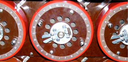
The three indicator drums
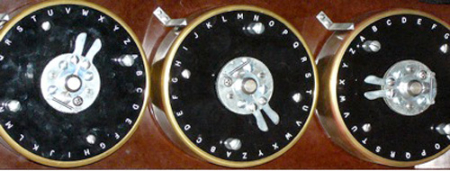
Bombe indicator drums. Note the clockwise sequence of letters on the fixed reference rings.
At each bombe ‘stop’ the ‘rotor core starting positions’ are read from three special gold coloured ‘indicator drums’ that are located on the right-hand side of the middle bank of drums. These special drums have circular reference scales on their faces similar to those on the other drums, but with the letters marked in the reverse order!
The scales on the three indicator drums are designed to show the ‘rotor core starting positions’ at a ‘stop’ when measured in terms of the corresponding Enigma ring-settings for the Enigma rotor settings: ZZZ. This is the reason why the letters on the scales on the indicator drums are in the reverse order to those on all the other drums.
This apparently perverse convention was originally used because it greatly reduced the chances of errors occurring during the subsequent work of checking the ‘stops’ carried out by hand on the checking machine.
This menu produced two stops for the known rotor order, one subsequently being identified as ‘false’, while the other gave a part of the original Enigma key that had been used. The information provided at the correct stop is as follows:
Rotor order: II , V , III; rotor core starting positions D K X; and the stecker pair G/Q.
By means of the checking machine the other letters on the menu provided the following additional seven stecker pairs A/D, E/T, H/M, L/J, N/V, U/F, and Z/P, together with three of the six ‘self-steckers’ R/R, S/S, W/W.
Indicator unit. The unit has three independent sets of twenty-six relays.
The ninth and tenth stecker pairs (X/O and I/K) were found from the letters in the crib that had not been used on the menu. With an Enigma machine set up with this rotor order, the ring-settings ZZZ, rotor starting positions DKX and the ten steckers given above, the machine correctly deciphered all the cipher letters that appear in the crib.
This outcome shows that an Enigma middle rotor ‘turn-over’ had not occurred up to this point when the message was originally enciphered. However since no other letters of cipher from this message are available, it is not possible to complete the task by finding the true ring-settings and the original message settings, as could be done with a longer message. Nevertheless it was a cause of great satisfaction to observe the machine in action for the first time and see it was able to find the correct ‘stop’.
Illustration credits
All images appear courtesy of the author.